Your source for Marshall and Soldano SLO mods!
Ground Zero Add-a-Stage install guide
Below you will find resources to install your Add-a-Stage
In this section you will find schematics and other information designed to assist you in adding an extra tube gain stage to your favorite amp. As always, proper safety protocols involving high voltage amps should be practiced. Installs should only be performed by qualified technicians.


Add-a-Stage schematic
Utilize the above schematic to reference component positions on the Add-a-Stage PCB
This is the general layout of the Add-a-Stage board. The values are general references, and what will be provided on assembled boards, unless specific substitutions are requested. This is a common schematic used for a gain stage in front of a tube preamp.
Any of the schematic values can be adjusted based on the circuit it's going on front of. There are lots of possibilities here.
Each component has a reference assigned to it (for example, "R1" for the input resistor). These references correlate to the component pads on the PCB. These can be used to easily and accurately populate the PCB. Care must be taken so that the electrolytic filter capacitor is oriented in the correct polarity.
Note that capacitor C4 is optional and cuts some high end from the voltage divider at the output of the stage. This will typically tighten the bass response as well. This can be useful if the stage sounds a bit too wild or fat sounding. The C4 capacitor will not be included on assembled boards, unless requested.

Add-a-Stage board layout
Using this layout, in conjunction with the above schematic should make for accurate assembly of the Add-a-Stage PCB.
Again, all values are subject to personal preference.
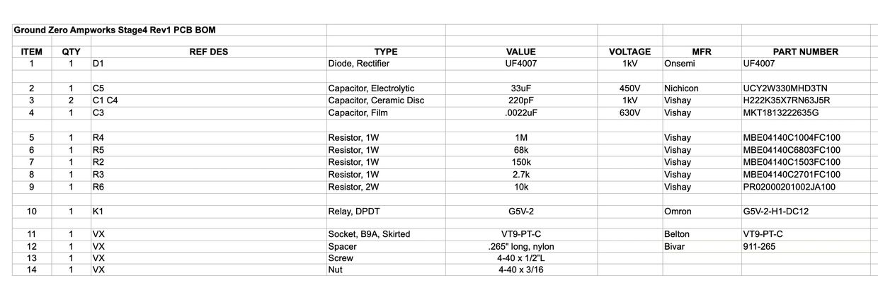
Add-a-Stage BOM
This is a general reference guide for components to complete one Add-a-Stage PCB.
Vishay PRO2 resistors are a good choice in addition to the MBE series listed.
A WIMA .0022uF capacitor with a 630vdc rating and 10mm lead spacing is a good substitute for C3.
Amplified Parts/ CE Distribution will carry the VT9-PT-C tube socket.
Most all other parts can be sourced from Mouser.com